In the past I had added relays on my car for the horn, accessory power and ignition power but was not happy with the aesthetics of my implementation. The relays were in a box that was not terribly accessible, the power wires were all separate an hanging off the solenoid and it just looked cruddy. I also wanted to add a couple more relays for the headlights. After some research, I found that the late 80’s and early 90’s Nissan vehicles used modular relay carriers that also accommodated fuses.
The plastic carriers have “slots” that accommodate relay sockets and fuse carriers. The relay type is defined by the relay color. I’ve documented the basic features and pinouts of the relays I’m working with here.
In planning the retrofit, I decided that I wanted the following functions supported by the new relay assembly:
-
•Accessory Power (one relay and fuse)
-
•Ignition Power for my DuraSpark box (two relays, one fuse)
-
•Horn (one relay, one fuse)
-
•Headlights (two low beam relays and two low beam fuses, one high beam relay and one fuse)
This plan requires a total of seven relays and six fuses. This all fits into the 10 compartment Maxima relay module and leaves me with 1 compartment open for “something else” in the future. Life is GOOD!
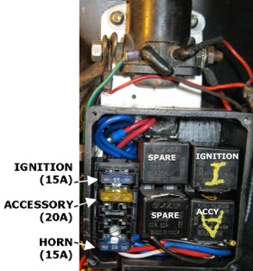
But, after all that work, I chickened out and decided that I did not want to do the extensive wiring changes I would need to do to put the new relays in. Instead, I found a small fuse block at the local O’Reilly’s and put that into the black box with the relays. I also relocated the box to a plate just below the solenoid and installed a bolt on the side of the box to accept power from the battery/solenoid. I connected the internal side of the bolt to the fuse block. I connected the wires feeding power to the relays (these were previously outside the box) to the fuse block inside the box and everything looks a bit tidier now. Then I took a photo of the box and labeled the parts on the graphic, laminated it in plastic and pasted it to the inside of the box cover so I’ll know what belongs to what.
I did new schematics so that I’d have some clue of how it’s wired if I have to maintain it in the future.